
relief
-
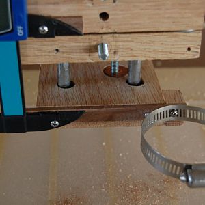
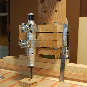
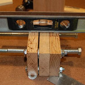
PIC 42 - Step 11c
I had to add a span so there was space between the Foredom Handpiece and the clamp SEE Followup Comments on Step 5. Pre-drill the holes on the clamp and the wood.- MT native
- Media item
- carving drill foredom homemade jig press relief
- Comments: 0
- Album: Homemade Relief Carving Jig
-
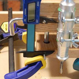
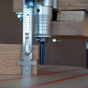
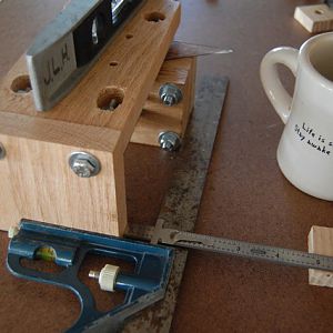
PIC 41 - Step 10b&c
Pre-drill holes in the wood with a 1/16in bit to prevent splitting. The clamp helps to hold the Gauge parallel for pre-drilling the wood. Use #6 x 1/2in screws to attach the gauge to the jig.- MT native
- Media item
- carving drill foredom homemade jig press relief
- Comments: 0
- Album: Homemade Relief Carving Jig
-
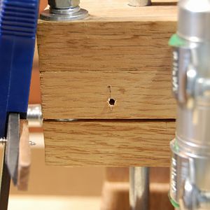
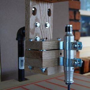
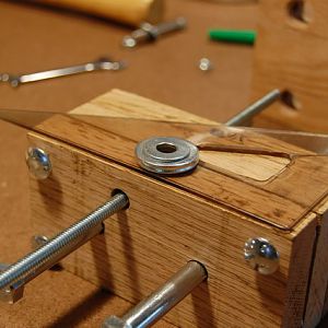
PIC 40 - Step 10a
The backs of the Gauge are not even so a spacer was added behind the end piece so it would be flush with the front of the jig.- MT native
- Media item
- carving drill foredom homemade jig press relief
- Comments: 0
- Album: Homemade Relief Carving Jig
-

WIP - Homemade Foredom Relief Carving Jig
INTRODUCTION I carve in-the-round. Now I want to do relief carving, with power tools. All of my web-based research repeatedly mentions the use of a router to ‘hog out’ the background wood in relief carvings. I do not own a router. I do not own a Dremel nor its plunge router base. The Foredom...- MT native
- Thread
- carving foredom homemade jig relief wip
- Replies: 31
- Forum: Woodcarving
-
PIC 39 - Step 9
Run Test - IT WORKS!! I never doubted it would (haha) - NEXT STEP add a depth gauge and hose adaptor to dust collector- MT native
- Media item
- carving drill foredom homemade jig press relief
- Comments: 0
- Album: Homemade Relief Carving Jig
-
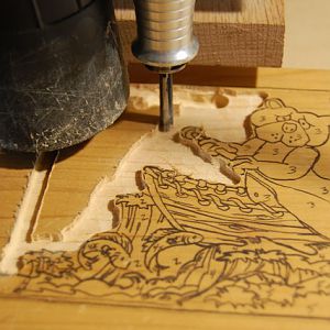
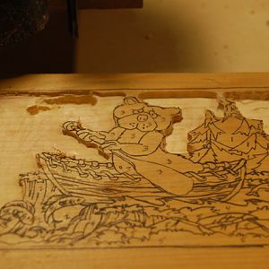
PIC 38 - Step 9
Run Test - I tried various depth cuts (back-left corner) before routing out an area at one depth- MT native
- Media item
- carving drill foredom homemade jig press relief
- Comments: 0
- Album: Homemade Relief Carving Jig
-
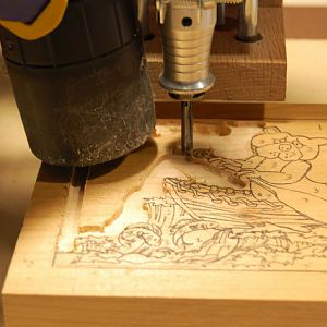
PIC 37 - Step 9
Run Test - I have no idea how deep the bit is but the wet-vac is working great- MT native
- Media item
- carving drill foredom homemade jig press relief
- Comments: 0
- Album: Homemade Relief Carving Jig
-
PIC 36 - Step 9
Run Test - It's ALIVE!! Dr. Frankenstein- MT native
- Media item
- carving drill foredom homemade jig press relief
- Comments: 0
- Album: Homemade Relief Carving Jig
-
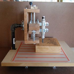
PIC 35 - Step 9
Side View - Homemade Foredom Relief Carving Jig- MT native
- Media item
- carving drill foredom homemade jig press relief
- Comments: 0
- Album: Homemade Relief Carving Jig
-
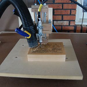
PIC 34 - Step 9
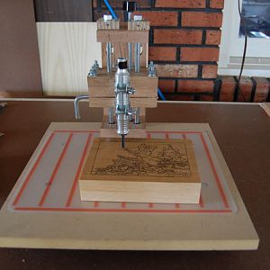
Front View - Homemade Foredom Relief Carving Jig. Depth Gauge and Dust Collector Hose still to be added.- MT native
- Media item
- carving drill foredom homemade jig press relief
- Comments: 0
- Album: Homemade Relief Carving Jig
-
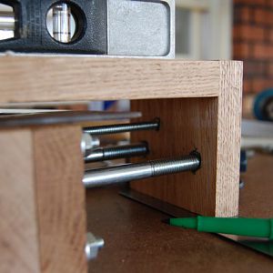
PIC 33 - Step 8
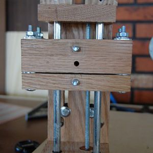
Jig Assembly - penny on bottom of Z-axis Support acts as a stop for the Depth Adjustment Rod- MT native
- Media item
- carving drill foredom homemade jig press relief
- Comments: 0
- Album: Homemade Relief Carving Jig
-
PIC 32 - Step 8
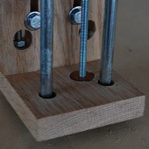
Jig Assembly - one 'Guide' bolt cut to size and channels cut in back of Z-axis Support so height above table can be adjusted.- MT native
- Media item
- carving drill foredom homemade jig press relief
- Comments: 0
- Album: Homemade Relief Carving Jig
-
PIC 31 - Step 8
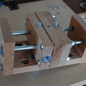
Assemble the Jig- MT native
- Media item
- carving drill foredom homemade jig press relief
- Comments: 0
- Album: Homemade Relief Carving Jig
-
PIC 30 - Step 7b
Figuring out how much height adjustment I can get (using scrap wood spacers) before cutting channels in the ‘spine’- MT native
- Media item
- carving drill foredom homemade jig press relief
- Comments: 0
- Album: Homemade Relief Carving Jig
-
PIC 29 - Step 7b
If Z-axis Support were raised 1/2in then a max 1.5in block could be hogged-out to depth to 1/2in from bottom- MT native
- Media item
- carving drill foredom homemade jig press relief
- Comments: 0
- Album: Homemade Relief Carving Jig
-
PIC 28 - Step 7a
Dry Fit to Frame to determine height above the table – Bit touches table NOT GOOD- MT native
- Media item
- carving drill foredom homemade jig press relief
- Comments: 0
- Album: Homemade Relief Carving Jig
-
PIC 27 - Step 6d
Mark where the holes will be drilled. Repeat leveling, centering and marking for other end- MT native
- Media item
- carving drill foredom homemade jig press relief
- Comments: 0
- Album: Homemade Relief Carving Jig
-
PIC 26 - Step 6c
Make sure the Carriage is centered and square to the Z-axis Support. COFFEE HELPS ME THINK- MT native
- Media item
- carving drill foredom homemade jig press relief
- Comments: 0
- Album: Homemade Relief Carving Jig
-
PIC 25 - Step 6b
Add spacers to simulate the travel clearance you will have between the bolt heads in the Carriage and the ‘spine’ of the Z-axis Support- MT native
- Media item
- carving drill foredom homemade jig press relief
- Comments: 0
- Album: Homemade Relief Carving Jig
-
PIC 24 - Step 6a
Level the Carriage FRONT SIDE DOWN- MT native
- Media item
- carving drill foredom homemade jig press relief
- Comments: 0
- Album: Homemade Relief Carving Jig