
You are using an out of date browser. It may not display this or other websites correctly.
You should upgrade or use an alternative browser.
You should upgrade or use an alternative browser.
Queen Anne Desk
- Thread starter creasman
- Start date
OP
OP
Case Joinery
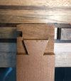
It always surprises me how much effort goes into something you never see. That's certainly true with the joinery for this desk. This is not something I'm willing to cut corners while doing, though. This is the stage that will make or break a project. I take great care to make sure the joints fit and are square, assembling and disassembling many times before opening the glue bottle.
This desk has a lot going on as far as the construction of the case. There are 30 mortise and tenons cut for joining the panels. Most of these are in the legs, with a few more on the inside knee hole corners. These also have a shallow (5/16") groove cut to keep the panels aligned so they will blend seamlessly into the legs. Add to these another 12 mortise and tenons for the drawer dividers and internal supports. Finally, there are 8 fairly large dovetails in the top and bottom dividers. None of this will be visible in the end.
I read somewhere once that, "If you want to do good joinery, use a sharp pencil. If you want to do great joinery, use a knife." My marking knife is indispensable when I'm laying out where to cut, where a mortise goes or simply aligning two parts. If you look closely at period furniture you can often spot these marks, a hint at how a joint was constructed.


In addition to being an imperceptibly fine line the scored mark offers a place to register your chisel as you cut, ensuring you are cutting exactly where you should. In this picture I'm using a 2" chisel to do the final cut on the shoulder of a panel. The initial cut was made about 1/16" from the shoulder. The chisel was then registered in the knife mark to make the final cut. By tilting the chisel 1 to 2 degrees you undercut the shoulder slightly and get tighter joint.

Besides a marking knife you see this principle at work in other tools. For example, I use a panel gauge to correctly size the panels, by planing the first edge square, then scoring a knife line at the height of the panel. I then plane to the point where this line just disappears. Another example is with the use of a marking gauge to lay out both the mortise and the tenons.


Joinery on the legs began with a 5/16" groove for the panel. I used the router table to cut these as it's much easier to start and stop at a point. Even so it was a bit tricky in that the top sections are 2" square, but the largest diameter at the foot is 2-1/4". To get around the foot preventing the leg from sliding all the way I had to shim both the table and the fence with 1/8" material (double-sided tape holds the bottom shim to the table).

This groove is only 5/16" deep, except for where a tenon will go. There are three tenons where each panel joins. Since I have so many of these to make I began by making a story stick ("T" is for tenon). This speeds up the layout and minimizes the chance of making an error. I use it on both legs and panels. You'll also notice I'm big on labeling things, like "Left inside front" to remind me this is the front end of the left interior panel.


I've gotten a lot of use out of the Moxon vise I made a few years ago. It's wide enough to hold the panel for sawing the tenons.


There is a top rail that runs the full length of the desk at the front. This supports the top and locks the sides of the desk together in front. Likewise, there are smaller bottom rails underneath the drawers to join the knee well panels to the legs. I could have mortised these, but dovetails seemed a better choice.


One of the rewards of all the effort is a first look at the desk. I've assembled and disassembled sections of the desk many times by this point. Finally, with all parts fitting I can pull the whole frame together (This is where I can show the "client" that all that noise was producing something). With the exception of a few clamps the case is able to stay together on its own.


I still have a bit more interior work before I can begin gluing the sections together. I want to make sure I have done everything necessary while I can still take it apart. It's very frustrating when you've already glued up a section only to discover you forgot something, like boring a hole, installing a drawer support, etc., and now it's impossible to easily access.
It always surprises me how much effort goes into something you never see. That's certainly true with the joinery for this desk. This is not something I'm willing to cut corners while doing, though. This is the stage that will make or break a project. I take great care to make sure the joints fit and are square, assembling and disassembling many times before opening the glue bottle.
This desk has a lot going on as far as the construction of the case. There are 30 mortise and tenons cut for joining the panels. Most of these are in the legs, with a few more on the inside knee hole corners. These also have a shallow (5/16") groove cut to keep the panels aligned so they will blend seamlessly into the legs. Add to these another 12 mortise and tenons for the drawer dividers and internal supports. Finally, there are 8 fairly large dovetails in the top and bottom dividers. None of this will be visible in the end.
I read somewhere once that, "If you want to do good joinery, use a sharp pencil. If you want to do great joinery, use a knife." My marking knife is indispensable when I'm laying out where to cut, where a mortise goes or simply aligning two parts. If you look closely at period furniture you can often spot these marks, a hint at how a joint was constructed.
In addition to being an imperceptibly fine line the scored mark offers a place to register your chisel as you cut, ensuring you are cutting exactly where you should. In this picture I'm using a 2" chisel to do the final cut on the shoulder of a panel. The initial cut was made about 1/16" from the shoulder. The chisel was then registered in the knife mark to make the final cut. By tilting the chisel 1 to 2 degrees you undercut the shoulder slightly and get tighter joint.
Besides a marking knife you see this principle at work in other tools. For example, I use a panel gauge to correctly size the panels, by planing the first edge square, then scoring a knife line at the height of the panel. I then plane to the point where this line just disappears. Another example is with the use of a marking gauge to lay out both the mortise and the tenons.
Joinery on the legs began with a 5/16" groove for the panel. I used the router table to cut these as it's much easier to start and stop at a point. Even so it was a bit tricky in that the top sections are 2" square, but the largest diameter at the foot is 2-1/4". To get around the foot preventing the leg from sliding all the way I had to shim both the table and the fence with 1/8" material (double-sided tape holds the bottom shim to the table).
This groove is only 5/16" deep, except for where a tenon will go. There are three tenons where each panel joins. Since I have so many of these to make I began by making a story stick ("T" is for tenon). This speeds up the layout and minimizes the chance of making an error. I use it on both legs and panels. You'll also notice I'm big on labeling things, like "Left inside front" to remind me this is the front end of the left interior panel.
I've gotten a lot of use out of the Moxon vise I made a few years ago. It's wide enough to hold the panel for sawing the tenons.
There is a top rail that runs the full length of the desk at the front. This supports the top and locks the sides of the desk together in front. Likewise, there are smaller bottom rails underneath the drawers to join the knee well panels to the legs. I could have mortised these, but dovetails seemed a better choice.
One of the rewards of all the effort is a first look at the desk. I've assembled and disassembled sections of the desk many times by this point. Finally, with all parts fitting I can pull the whole frame together (This is where I can show the "client" that all that noise was producing something). With the exception of a few clamps the case is able to stay together on its own.
I still have a bit more interior work before I can begin gluing the sections together. I want to make sure I have done everything necessary while I can still take it apart. It's very frustrating when you've already glued up a section only to discover you forgot something, like boring a hole, installing a drawer support, etc., and now it's impossible to easily access.
Attachments
OP
OP
I did not. However, it wouldn't matter with this client. They have an unwritten prerogative that allows them to change their mind at any time and for any reason.I must ask, though, did you get the "customer" initial the design drawings before going to production?
OP
OP
Thanks. Good observation, and question. I'll have more to say on this in an upcoming post. The general plan is to only glue the bottom tenon on these panels. That's because I need the bottom to remain fixed so shrinkage does not separate it from the trim around the base. The top third of the panel will only be attached via the pins. These will be inserted into elongated holes to allow some movement.Question, on that wide panel will you glue all three tenons or just one to allow for movement?
OP
OP
Pegging the Sides
It's finally time to start putting some square pegs in round holes. By that I mean making some dowels and pegging the desk sides to the legs. For the first step I used my dowel plate that I wrote about earlier. The blanks are riven rather than sawn so the grain in each peg is straight. I inserted each peg into a pencil sharpener so the first 1/8" was tapered to make them easier to insert.
There is something therapeutic about making these -- starting with a square blank and driving it through successively smaller holes until you get the right size. I've gone through a couple of dozen so far on the sides and will need to make a few more before joining the back. I'm actually looking forward to it.

A supply of 1/4" pegs at the ready, the next step is to mark the holes in the legs and side pieces. I used the story stick again to speed the process and make sure all holes were in the correct spot.

After boring the holes in the legs, I reassembled and clamped the side pieces in order to mark the location of the tenons. Here's where the magic of this type of joint begins to happen. Rather than bore straight through leg and tenon, I want the holes in the tenon to be closer to the shoulder. Thus, the act of driving the peg into the hole actually pulls the joint tighter together.
In my case the holes are 1/4" in diameter and I wanted the tenon holes offset by 1/32". To mark the center of each I used a 3/16" center punch held against the shoulder side of the leg hole. Notice how the resulting mark is off-center from the hole. Just make sure you hole the punch correctly, or the reverse effect will be true.


I only want glue on the bottom tenon. This equates to roughly the bottom third of the panel being glued. The top two tenons are held in place only by pegging. This is to allow the panels to expand and contract with changes in humidity. I also have to elongate the holes in the top two tenons for this to happen. I used a round file to expand each about 1/16" in either direction.

After applying glue, assembling the parts and clamping everything in place, I drove a peg in each hole. Just before the peg hit bottom I applied a dab of glue -- just enough so the peg would hold, but not too much to allow glue into the joint. I glued the bottom peg completely.
In these pictures you can see the steps:


I really like the effect these make. They're just visible enough to make an honest statement about how this joint is made. There is an excellent article in Fine Woodworking magazine #191 (June 2007) on pegged joints in furniture. It gives a lot of options and practical advice.
It's finally time to start putting some square pegs in round holes. By that I mean making some dowels and pegging the desk sides to the legs. For the first step I used my dowel plate that I wrote about earlier. The blanks are riven rather than sawn so the grain in each peg is straight. I inserted each peg into a pencil sharpener so the first 1/8" was tapered to make them easier to insert.
There is something therapeutic about making these -- starting with a square blank and driving it through successively smaller holes until you get the right size. I've gone through a couple of dozen so far on the sides and will need to make a few more before joining the back. I'm actually looking forward to it.
A supply of 1/4" pegs at the ready, the next step is to mark the holes in the legs and side pieces. I used the story stick again to speed the process and make sure all holes were in the correct spot.
After boring the holes in the legs, I reassembled and clamped the side pieces in order to mark the location of the tenons. Here's where the magic of this type of joint begins to happen. Rather than bore straight through leg and tenon, I want the holes in the tenon to be closer to the shoulder. Thus, the act of driving the peg into the hole actually pulls the joint tighter together.
In my case the holes are 1/4" in diameter and I wanted the tenon holes offset by 1/32". To mark the center of each I used a 3/16" center punch held against the shoulder side of the leg hole. Notice how the resulting mark is off-center from the hole. Just make sure you hole the punch correctly, or the reverse effect will be true.
I only want glue on the bottom tenon. This equates to roughly the bottom third of the panel being glued. The top two tenons are held in place only by pegging. This is to allow the panels to expand and contract with changes in humidity. I also have to elongate the holes in the top two tenons for this to happen. I used a round file to expand each about 1/16" in either direction.
After applying glue, assembling the parts and clamping everything in place, I drove a peg in each hole. Just before the peg hit bottom I applied a dab of glue -- just enough so the peg would hold, but not too much to allow glue into the joint. I glued the bottom peg completely.
In these pictures you can see the steps:
- Drive the peg in until it hits the bottom of the hole.
- Use a thin scrap when sawing off the excess to 1) avoid scratching the surface and 2) leave about 1/16" of the peg proud.
- Wet the end of the peg (I used thinned glue) and mushroom the head to force it to expand and fill any gaps.
- Work around the peg with a sharp chisel to shear it off even with the surface.
I really like the effect these make. They're just visible enough to make an honest statement about how this joint is made. There is an excellent article in Fine Woodworking magazine #191 (June 2007) on pegged joints in furniture. It gives a lot of options and practical advice.
OP
OP
Edge Mouldings (cont)
Been a busy week, but I did manage to complete the second moulding plane for the project. This one cuts the same profile as the first, only smaller. This will create the edge around the base of the desk and mirror the one around the desk top. Both are QS cherry.

The collection is growing...

Been a busy week, but I did manage to complete the second moulding plane for the project. This one cuts the same profile as the first, only smaller. This will create the edge around the base of the desk and mirror the one around the desk top. Both are QS cherry.
The collection is growing...
OP
OP
Case Assembled
I have the case assembled and glued now. Though I glue in stages there comes a point when you have to push forward. In other words, you've reached the last stage and everything remaining has to go together -- now. Once the glue hits a joint the clock is ticking. You have a limited amount of time to assemble all the parts, set the clamps, then check and adjust for alignment before the glue sets.
Megan Fitzpatrick jokes that the collective IQ in the room drops with every glue bottle open. We've probably all experienced that panic to some degree. This is why it's important to do a dry run without glue when assembling a large project. Once the glue bottle is open I don't want any surprises. I want to know the order I will follow when connecting the parts, I want to know they fit, and I want to know they align. I want my clamps out and adjusted to the right size, and I want my assembly mallet nearby. Like when the professor starts the exam, you want scratch paper and extra pencils at the ready.
Fortunately, it all went together exactly as planned. I took the clamps off this morning and checked again for square by measuring the diagonals. On a project this size I consider it a win if they are within 1/16". They measured exactly the same. Some other things that help with case construction:
- Glue on a flat surface. The assembly table shown in the picture is both flat and level.
- If you start square then it's easier to end up square. If the individual parts are square and fit, the project squares itself as it is clamped together.
- I use liquid hide glue (Old Brown Glue). You have to warm it before using (I put the bottle in a bowl of hot tap water a few minutes first), but it has an extended open time before it sets. I also don't worry about getting glue on the piece. Like hot hide glue it doesn't affect the finish if I miss a spot when cleaning up.
Looking great. Keep the updates coming!
OP
OP
Bottom Trim
The project has a moulded trim that runs around the base of cabinet just above the turned legs. Like the hem on a skirt it gives the piece a more finished look. I used the smaller of the two planes to make about 20' of moulding. This is the most I've ever made by hand at one time. The back piece is five feet in length, making it the longest section of moulding I've made with hand planes as well.
One of the keys to effectively using moulding planes is to provide adequate support for the work piece while you plane. The stock in this case is only 1-1/2" wide by 5/8" thick and can easily flex if not supported. The classic support fixture to use is called a sticking board, and consists of a rigid base, fence and end stop to prevent the piece from moving.
My sticking board has an adjustable fence. The end stops are screws that can be raised or lowered to keep them below the planing action. The fence needs to be high enough to support the work piece without getting in the way. Three bolts hold the fence. These can be easily loosened to adjust the fence. I typically position the fence so the blank is just up to the edge.


Selecting the right piece of wood is crucial. You want the best stock you have for making moulding, with clear, straight grain. Before starting to plane look carefully at the grain. Usually there is one corner where the grain is predominately running up from the bottom and towards the front edge. That's the corner to use. Below is an illustration from Matthew Bickford's book, Mouldings in Practice (a recommended read).

One of the challenges on this project is that the sticking board I have is only 42" long. I had to extend this by clamping a temporary block about a foot beyond the end (as shown in the distance). I start at the end where the stop is and work my way towards the back. It's easier to plane in sections rather than try running the full length. Once the profile is cut the entire length I ran the plane the full length with light pressure to be sure there weren't any high spots remaining. The last thing I'll say is keep your eye (and mind) on the spring line so the plane stays at the proper angle.

This trim is profiled on both top and bottom, with the same plane able to cut both designs. I first cut the top profile (the cove plus round-over), then flipped the piece and cut just the round-over on the bottom. This gives it a bull-nose edge. For the bottom you have to stop just before it begins to cut the fillet. It's not as hard as it might sound. Just use light pressure and pay attention to how it looks after each pass.


The final step is to burnish the moulded edge using the shavings. Grab a handful and rub over the profile several passes. This polishes the wood and removes any fine splinters. Moulding cut using a plane should not be sanded. Sanding is bad as it can destroy the crisp lines left by the plane. If you have rough spots use a small scraper and feather these out by hand, then burnish with shavings. You will have plenty of shavings.


I was surprised by how much I worked up a sweat doing this, even with a sharp plane. As the plane cuts deeper more of the iron is cutting. By the time you reach the stop you are removing shavings up to an inch wide -- a shop work out.
Next up is installing the trim. This will require some work to the cabinet as the first step, then carefully cut miters as it wraps around the cabinet. Stay tuned...
The project has a moulded trim that runs around the base of cabinet just above the turned legs. Like the hem on a skirt it gives the piece a more finished look. I used the smaller of the two planes to make about 20' of moulding. This is the most I've ever made by hand at one time. The back piece is five feet in length, making it the longest section of moulding I've made with hand planes as well.
One of the keys to effectively using moulding planes is to provide adequate support for the work piece while you plane. The stock in this case is only 1-1/2" wide by 5/8" thick and can easily flex if not supported. The classic support fixture to use is called a sticking board, and consists of a rigid base, fence and end stop to prevent the piece from moving.
My sticking board has an adjustable fence. The end stops are screws that can be raised or lowered to keep them below the planing action. The fence needs to be high enough to support the work piece without getting in the way. Three bolts hold the fence. These can be easily loosened to adjust the fence. I typically position the fence so the blank is just up to the edge.
Selecting the right piece of wood is crucial. You want the best stock you have for making moulding, with clear, straight grain. Before starting to plane look carefully at the grain. Usually there is one corner where the grain is predominately running up from the bottom and towards the front edge. That's the corner to use. Below is an illustration from Matthew Bickford's book, Mouldings in Practice (a recommended read).
One of the challenges on this project is that the sticking board I have is only 42" long. I had to extend this by clamping a temporary block about a foot beyond the end (as shown in the distance). I start at the end where the stop is and work my way towards the back. It's easier to plane in sections rather than try running the full length. Once the profile is cut the entire length I ran the plane the full length with light pressure to be sure there weren't any high spots remaining. The last thing I'll say is keep your eye (and mind) on the spring line so the plane stays at the proper angle.
This trim is profiled on both top and bottom, with the same plane able to cut both designs. I first cut the top profile (the cove plus round-over), then flipped the piece and cut just the round-over on the bottom. This gives it a bull-nose edge. For the bottom you have to stop just before it begins to cut the fillet. It's not as hard as it might sound. Just use light pressure and pay attention to how it looks after each pass.
The final step is to burnish the moulded edge using the shavings. Grab a handful and rub over the profile several passes. This polishes the wood and removes any fine splinters. Moulding cut using a plane should not be sanded. Sanding is bad as it can destroy the crisp lines left by the plane. If you have rough spots use a small scraper and feather these out by hand, then burnish with shavings. You will have plenty of shavings.
I was surprised by how much I worked up a sweat doing this, even with a sharp plane. As the plane cuts deeper more of the iron is cutting. By the time you reach the stop you are removing shavings up to an inch wide -- a shop work out.
Next up is installing the trim. This will require some work to the cabinet as the first step, then carefully cut miters as it wraps around the cabinet. Stay tuned...
OP
OP
Installing the Bottom Trim
In David Pye's book, The Nature and Art of Workmanship, he describes a concept he calls "workmanship of risk." He defines this as "workmanship using any kind of technique or apparatus, in which the quality of the result is not predetermined, but depends on the judgment, dexterity and care which the maker exercises as he works" (The Nature and Art of Workmanship, p. 4). Every woodworker experiences the angst this can cause at one time or another. Moreover, the risk (of messing up an entire project) only increases the further along we are. It's the source of the thrill that keeps us coming back into our shops, or grief that can cause us to take a long hiatus.
Installing the trim around the desk was one of these angst moments for me. If I miscut a piece as I'm assembling a cabinet, then I will just cut another. No big deal, other than wasting some material. The preparation for installing the trim, however, involves cutting into the desk as it is already assembled. Mistakes get harder to fix -- aka, workmanship of risk. Each corner (six) on the desk is rounded and a notch is cut into each leg for the trim. After the trim is installed, then each corner has to be rounded so it flows evenly around the sides. Like the sign you see when driving in the mountains...

The journey begins by marking where the notch will be cut into the leg. I mark these now while the edge of the leg is still square. However, I only saw the sides of each notch at this time. Fully excavating the notch would leave the bottom corner with little support. It could easily be broken off during the rounding. At this time I marked the curve (white pencil) on each end and penciled lines down the length of each corner as a guide. These aren't the termination of the curve, but rather mark the extent of the starting chamfer as shown in the last image.


The radius of these curves is 1". After making the chamfer I used a #15 (1-1/8" radius) hollow moulding plane to cut the rest. A template made from an old saw blade was used both as a guide to check the curve as well as a scraper to smooth out any high spots.


Once the corners were rounded and sanded I felt safe to finish the notches. These are cut just deep enough to allow the miter on the trim to extend below the curve, and fully hide the back of the joint. I hope this gives you a sense of the "risk". There is no going back from this sort of step.


Finally, ready to fit the trim. The angst level is lower for this. Again, I am adding pieces so worst case is I miscut. The main risk is I only made enough moulding to go around once. A mishap would mean planing another section, so really just time and material. I won't go into a lot of detail. This involves cutting some interesting angles and notches as you work around the base. I began with the back piece, then the two insides (knee well), then outsides and finally the front pieces. Nothing was glued until I had every piece fitting the way I wanted. As for gluing only the corners are glued. Screws hold the rest in place.


I happened to find a box of vintage #10 1-1/4" wood screws at an estate sale. I was thrilled when they told me the price was 75 cents.

After a straight section in the road there were more curves. The final step is to carve the moulding around each corner. The angst level increased again as yet another opportunity to mess up the project loomed. I didn't concern myself with how the moulded edges met since these are carved away. I did want a good miter joint.
There are six corners to round. I find that following the same process is the best way to produce identical results. Also, I chose a back corner as the place to figure out this process. I carved by starting at the top and working down, or from the inside to the outside, however you want to think about it. The grain changes (abruptly) at the miter so you have to work from start to middle on each curve.


The tools used are shown below.

I'm pleased with the results. The effect is that the trim flows around the base, tracing the curves on the sides. The client (aka, wife) does not like sharp corners, so she is pleased as well -- win-win.

The remaining elements are the drawers and top. I'm still in the design phase on how these will look. My plan is to make some samples to review with the client before deciding.
In David Pye's book, The Nature and Art of Workmanship, he describes a concept he calls "workmanship of risk." He defines this as "workmanship using any kind of technique or apparatus, in which the quality of the result is not predetermined, but depends on the judgment, dexterity and care which the maker exercises as he works" (The Nature and Art of Workmanship, p. 4). Every woodworker experiences the angst this can cause at one time or another. Moreover, the risk (of messing up an entire project) only increases the further along we are. It's the source of the thrill that keeps us coming back into our shops, or grief that can cause us to take a long hiatus.
Installing the trim around the desk was one of these angst moments for me. If I miscut a piece as I'm assembling a cabinet, then I will just cut another. No big deal, other than wasting some material. The preparation for installing the trim, however, involves cutting into the desk as it is already assembled. Mistakes get harder to fix -- aka, workmanship of risk. Each corner (six) on the desk is rounded and a notch is cut into each leg for the trim. After the trim is installed, then each corner has to be rounded so it flows evenly around the sides. Like the sign you see when driving in the mountains...
The journey begins by marking where the notch will be cut into the leg. I mark these now while the edge of the leg is still square. However, I only saw the sides of each notch at this time. Fully excavating the notch would leave the bottom corner with little support. It could easily be broken off during the rounding. At this time I marked the curve (white pencil) on each end and penciled lines down the length of each corner as a guide. These aren't the termination of the curve, but rather mark the extent of the starting chamfer as shown in the last image.
The radius of these curves is 1". After making the chamfer I used a #15 (1-1/8" radius) hollow moulding plane to cut the rest. A template made from an old saw blade was used both as a guide to check the curve as well as a scraper to smooth out any high spots.
Once the corners were rounded and sanded I felt safe to finish the notches. These are cut just deep enough to allow the miter on the trim to extend below the curve, and fully hide the back of the joint. I hope this gives you a sense of the "risk". There is no going back from this sort of step.
Finally, ready to fit the trim. The angst level is lower for this. Again, I am adding pieces so worst case is I miscut. The main risk is I only made enough moulding to go around once. A mishap would mean planing another section, so really just time and material. I won't go into a lot of detail. This involves cutting some interesting angles and notches as you work around the base. I began with the back piece, then the two insides (knee well), then outsides and finally the front pieces. Nothing was glued until I had every piece fitting the way I wanted. As for gluing only the corners are glued. Screws hold the rest in place.
I happened to find a box of vintage #10 1-1/4" wood screws at an estate sale. I was thrilled when they told me the price was 75 cents.
After a straight section in the road there were more curves. The final step is to carve the moulding around each corner. The angst level increased again as yet another opportunity to mess up the project loomed. I didn't concern myself with how the moulded edges met since these are carved away. I did want a good miter joint.
There are six corners to round. I find that following the same process is the best way to produce identical results. Also, I chose a back corner as the place to figure out this process. I carved by starting at the top and working down, or from the inside to the outside, however you want to think about it. The grain changes (abruptly) at the miter so you have to work from start to middle on each curve.
The tools used are shown below.
- Direct light for illumination and creating shadows. Contrast (light vs dark) help guide the work.
- 5/16" in-cannel gouge for carving the cove.
- 5/18 sweep for marking the fillet.
- 3/8" firmer chisel to clean up the fillet.
- 1" paring chisel to excavate the fillet and shape the outside curve.
- 7/16 sweep to round over the bullnose.
- Templates for tracing and checking the curves.
- Scrapers and sandpaper for cleanup.
- A handful of shavings for final burnishing.
I'm pleased with the results. The effect is that the trim flows around the base, tracing the curves on the sides. The client (aka, wife) does not like sharp corners, so she is pleased as well -- win-win.
The remaining elements are the drawers and top. I'm still in the design phase on how these will look. My plan is to make some samples to review with the client before deciding.
Last edited:
Premier Sponsors
Contact for your financial processing needs!
Our Sponsors
LATEST FOR SALE LISTINGS
-
 For Sale Electrical supplies (Are you building a new shop?)
- Started by DSWalker
- Replies: 0
-

-

-
-
 For Sale Powermatic PM 701 Mortiser, 4 Powermatic Chisels (3 unused in wrapper) $550
- Started by frankc4113
- Replies: 0