Is it time to replace my machines?

Willemjm

Willem
Corporate Member
I started my shop around 2003, probably purchased all my machinery by 2005. Smaller hand and power tools seem to be an ongoing purchase though.

I get by just fine, it is certainly not a mass production shop, but can do anything I need, just lengthy set up times due to the difference from one custom job to the next. I get by just fine without CNC, again we build mostly one off stuff, being things we can't buy in the market.

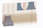
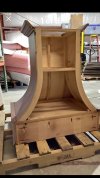
The biggest challenge so far was building a curved range hood, not laminated, out of 3/4 ply. CNC would have been a great help to mill those curves perfectlly, but I could not find anyone who have figured out the math to do the second set of curves. The production shops making those seem to preserve that as a top secret, they won't share. One guy mentioned they cut and bend the sides first, then use the CNC to scribe the bent curve and capture in the software. Sounded really complicated.

So in short, everything I have has been fully depreciated, around 20 years old. There has been little to no maintenance, but everything still works just fine.

Am I perhaps missing something?
 

Wiley's Woodworks

Wiley
Corporate Member
You didn't say why you are contemplating replacing machinery. IMO if a machine is operating properly--maintaining tolerances, not suffering recurring breakdowns, and parts are readily available if it does break--keep using it.

CNC machines are a whole different ballgame. I do not own one nor will I, but I have seen some amazing things done with one. Once the program is written, the speed and accuracy with which multiple components can be made is truly impressive. For a hobbyist it is a fun toy that brings with it its own set of challenges, if you're into that sort of thing with your woodworking. For a production shop, regardless of size, I think it will be essential. It's a case of if you don't have one you can't compete price-wise with someone who does have one.

CNC combined with laser engraving opens up a whole new world of customizing and personalizing finished pieces. I predict hand carving in wood will be a lost art in ten years. If you do find it, it will cost 10x what modern technology can produce, and no one can tell the difference.

Buying and setting up a CNC is only half the battle. You have to find and hire someone who can write programs quickly. This someone is probably from a younger generation whose background might be computer technology rather than traditional woodworking. Investigate your local community colleges for a woodworking program that teaches CNC or a technical skills or fabrication program that utilizes CNC technology. An added bonus is this person should be proficient at using Sketch Up for drawings. Again, the time savings is impressive, and you'll raise your confidence level in your presentations and bids because they will look so much more professional than conventional mechanical drawings, or none at all because they take so much time.

Digital technology is permeating the entire woodworking industry. It is a lot farther and deeper than sticking a Wixey angle gauge on a table saw blade to get that 22.5 degree bevel. Digital motor controllers have obsoleted the 2 belt/3 shaft speed changer in drill presses. Soft start motors make routers safer. Laser locators have increased the accuracy of power saws and drill presses. Pretty soon almost all mortise and tenon joinery will be cut using modern technology, and the joinery will be better than what you and I can produce in our finest moments. Digital scales on rip fences make a difference when replicating parts. Software on a thumb drive is rapidly replacing all those shop jigs, patterns, and fixtures you've got around your shop. It is ok if you can't or won't make the leap into 21st century technology in the woodworking industry, but your production shop will have to so it can survive. Hire the skills.

One last thought: Don't confuse the terms custom work, manufactured, production, and hand crafted. The most important outcome for a business is a satisfied customer. Second is a profit. How you got there is less important to the customer than what you installed in their home.
 
Last edited:

tvrgeek

Scott
Corporate Member
The only traditional shop machine that still works and needs replacing is if your table saw does not have a riving knife.
For CNC CAD tricks, go to the CNC maker forums, not cabinet shops. Math for curves is in fact tricky. Things that sound simple like how much gas is in a cylindrical tank on it's side? Requires calculus.
If I remember that far back, in engineering drafting we had to do a flat sheet intersection of an oval duct into the corner of a square. It was not easy.
 

Willemjm

Willem
Corporate Member
Willem,
Do you want to Kerf cut the 3/4 ply I guess? All 3 faces and miter the corners?
In the construction below, the two side pieces and the front piece are mitered with different angles at the bottom, that is the easy part. The angle depends on the slope.

The other sides of each piece,(front and two sides) are mitered at 45 degrees, also easy to do on a shaper with a 45 degree cutter.

The trick is getting the three pieces, (front and two sides) have their seams fit perfectly. The two side pieces are cut with their curves first, perfect to do on a CNC if available. Then the two side pieces are kerfed and bent with a retainer dado'd on the inside. To determine the differential equation of the front piece curves, which are cut prior to bending the ply is a challenge.

I have drawn that out on Solidworks, with the hope that I could get the front piece curves when cut on flat ply, no luck, software is not able to do that.

Range Hood.jpg
 

SJWiehe

Steve
Corporate Member
Your post intrigued me. There appear to be a number of people selling .dxf files on Etsy for range hood’s for about $150. Once you have the basic shape/geometry you can scale it as you need inside of Vectric Aspire. If you can get a dxf file I am happy to try to cut /assemble one for you on my cnc for nothing as I would appreciate the challenge.

I’m in Raleigh so I’m not too far away from you.

steve
 

Willemjm

Willem
Corporate Member
Your post intrigued me. There appear to be a number of people selling .dxf files on Etsy for range hood’s for about $150. Once you have the basic shape/geometry you can scale it as you need inside of Vectric Aspire. If you can get a dxf file I am happy to try to cut /assemble one for you on my cnc for nothing as I would appreciate the challenge.

I’m in Raleigh so I’m not too far away from you.

steve
There are two ways, the clean way is 3/4” ply. The other way needing a larger hood for the same internals, uses a framework, which is then laminated with two sheets of 1/4” MDF.

The plans I have seen are for the second method.

The second method is easier for the small shop, but I can get a 46” insert and blower into a 48” hood using the first method. Second method to make space for the framing, the hood needs to be 52” wide for 46” internals.
 

chris_goris

Chris
Senior User
Willem, I can create parametric hood shapes ( any shape or size or curvature ) on the fly by manipulating the control dimensions ( L X W X H and curvature control) as well as upper size ( L X W) easily. I can either CNC the shape or create a 2D dimensioned drawing of the flats . Now, I dont believe you can simply 45 degree machine the curve profile on the inside and have the corner come together seamlessly out of 3/4 material. My head is telling me its a variable angle on the curved section. Kind of like a tapered box doesnt have 45 degree corners. I would have to cut one and try it.
 

Willemjm

Willem
Corporate Member
Willem, I can create parametric hood shapes ( any shape or size or curvature ) on the fly by manipulating the control dimensions ( L X W X H and curvature control) as well as upper size ( L X W) easily. I can either CNC the shape or create a 2D dimensioned drawing of the flats . Now, I dont believe you can simply 45 degree machine the curve profile on the inside and have the corner come together seamlessly out of 3/4 material. My head is telling me it’s a variable angle on the curved section. Kind of like a tapered box doesnt have 45 degree corners. I would have to cut one and try it.
I have built one, the miter angle is 45 degrees. My challenge was cutting the curves on a bandsaw, so there were 1/16” gaps here and there. Built the sides, then scribed the front with 3/16” material clamped to the sides as a template.

We build a lot of tapered hoods, no curve, miter angles are 45 degrees.


With CNC, the part I have difficulty grasping is once I have created the parametric front in 3D CAD it is the exact curved piece. The moment it is layed flat, to cut it, those curves change somewhat.

When I scribe the front bent piece clamped to the sides, I have the exact profile. So no problem to lay the template down flat and cut along the scribed lines. How would you lay a curved piece flat in software, to emulate the changes in the curves?

IMG_2611.jpeg
 
Last edited:

Scott H

Scott
User
You may be able to use the sheet metal functions of some CAD software to take a 3D model and turn it into a flattened version. I know Fusion 360 has functionality for basically unfolding/laying flat models so that they could be cut/bent out of sheet metal. I do not use that much, though.

There are also plugins/functionality for general purpose modeling programs like Blender to convert models to paper templates (for e.g. papercraft), if you tessellated your model enough that might work too.

I am not sure how you actually print that out though, short of having a plotter or manually upscaling it using a grid. I guess you just CNC cut it directly onto a sheet of plywood?
 

chris_goris

Chris
Senior User
Looking at the one you built Willem, Im wondering have you been able to look at a factory built hood? dissect it? Maybe if its 3/4 material, its built crudely, gaps filled etc , then veneered to ensure tight outside corners?
 

chris_goris

Chris
Senior User
With CNC, the part I have difficulty grasping is once I have created the parametric front in 3D CAD it is the exact curved piece. The moment it is layed flat, to cut it, those curves change somewhat.

When I scribe the front bent piece clamped to the sides, I have the exact profile. So no problem to lay the template down flat and cut along the scribed lines. How would you lay a curved piece flat in software, to emulate the changes in the curves?

View attachment 227778
The way I would accomplish this is create a model (or models) based on another model. the second set would query the first for its exact dimensions. For instance, the first model is the finished outside shape desired. Now imagine if you will, creating parallel planes to the floor in your photo that horizontally slice your hood. That will generate lofted cross sections for each piece at any height. The second model in my method will query the first to know the exact length of the curved line as well as the height of the flattened piece based on again, querying the length of the first model. The flattened pattern can then be programmatically generated (lofted ) on the fly at any degree of accuracy or resolution you require ( the more slices, the more accurate) this can also be done simply with CAD tools.
 
Last edited:

Willemjm

Willem
Corporate Member
Looking at the one you built Willem, Im wondering have you been able to look at a factory built hood? dissect it? Maybe if its 3/4 material, its built crudely, gaps filled etc , then veneered to ensure tight outside corners?
Nope, the one I built was fixed with filler as it is impossible to get a perfect match cut on the bandsaw. It wasn't bad but there were 1/16" gaps here and there.

The ones we buy have those joints tight and perfect, they are CNC cut. The miter joint along the curve is tight and closed all the way.
 

chris_goris

Chris
Senior User
Nope, the one I built was fixed with filler as it is impossible to get a perfect match cut on the bandsaw. It wasn't bad but there were 1/16" gaps here and there.

The ones we buy have those joints tight and perfect, they are CNC cut. The miter joint along the curve is tight and closed all the way.
If I had a call for it I would set it up......
 

Willemjm

Willem
Corporate Member
I wonder what these fasteners are? and based on material thickness of 3/4" , Im guessing the kerf cuts are about 1/2" apart and they must be at least 5/8 deep? any idea? Something Id have to test and try
Correct, the kerfs are a hair below 5/8”. They use a combination core plywood, bends a little better.

I don’t know where they get the fasteners.

Note how the kerfs cut on the three pieces are all aligned.

The one I built, I pinned on the outside 23 gauge pin nails and then used hot melt glue on the inside.
 

chris_goris

Chris
Senior User
Correct, the kerfs are a hair below 5/8”. They use a combination core plywood, bends a little better.

I don’t know where they get the fasteners.

Note how the kerfs cut on the three pieces are all aligned.

The one I built, I pinned on the outside 23 gauge pin nails and then used hot melt glue on the inside.
Aligning all the kerfs is critical. Oddly enough, I saw one for sale on FB marketplace that appears to use 1/2" ply or maybe less with no Kerf cuts. It also uses the perimeter base trim to hide any sins on the bottom, this may be common practice.
 

Attachments

  • IMG_5859.jpg
    IMG_5859.jpg
    207.1 KB · Views: 26

Premier Sponsor

Our Sponsors

LATEST FOR SALE LISTINGS

Top