Christmas Present

JNCarr

Joe
Corporate Member
My daughter and son-in-law live in Montana and love to camp in their 32ft motor home. When I saw the NC map of state parks posted by @beloitdavisja, I was inspired to do a similar project but originally thought I'd do all the national parks. Through a series of sneaky questions, I figured out that they would better use a MT state parks map, so here it is.
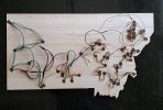
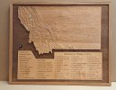
It's about 31-1/4 x 26-1/2 x 1-1/2. Made of hard maple, "sanded ply" from a big box, Baltic birch ply and oak. @kserdar lasered the legend.

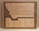
The two key features are the topological relief and the 55 LED indicators for the parks (and another 55 for the legend). The first picture shows the map in steady state with 10 parks set to "visited".
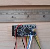
The knob on the left controls all the functions. If the knob is rotated without first pushing it, the base brightness of the LEDs is adjusted up or down.
To set a park to "visited", the knob is first pushed to enter the "set" mode. The upper left LED on the legend will light either red, if not previously visited or green if it has been visited. The LED on the map will also glow blue regardless if off or already green - this associates the legend name and the physical location. The knob is rotated until the desired name is located. This is shown in the second picture - note the LED next to "Tower Rock" is lit red, indicating not visited. Pushing the button will set the park to "visited" and the LED will turn green on both the legend and the map. If the park was already green, pushing the button turns it red and turns off the LED on the map. This toggle action can happen as often as desired.
The button can be rotated to another park and the same action taken. If there's no activity for 5 seconds, the system returns to display mode - the map stays on and the legend is dark.
All park information is saved to non-volatile memory so if the power is removed for whatever reason, the parks will be correctly displayed when power is returned.
There is a light sensor that varies the map LEDs up or down to accommodate ambient light and also turns the map LEDs off if the ambient is below a certain threshold. This is "additive" to the base brightness setting.
The other aspect is pushing the knob in for 10 seconds will reset all parks to off.
 

Attachments

  • Montana Map_1.jpg
    Montana Map_1.jpg
    3.3 MB · Views: 152
  • Legend in Use.jpg
    Legend in Use.jpg
    6.9 MB · Views: 167
Last edited:

beloitdavisja

James
Corporate Member
Hurray for another state park map! Looks great and very clean. I like the minimal UI - it's simple but very effective. I really like the ambient light sensor. That's a really nice touch. I'm sensitive to that since my wife can't stand having any type of light on to sleep (and by "light" i mean any kind of LED indicator light)

What are you using to control the LEDs & persistent storage? Arduino? Raspberry Pi? Other?
Battery powered?

Excellent job as always Joe. I'm sure they're going to be thrilled with hit.
 

drw

Donn
Corporate Member
Joe, the map is really a thoughtful, meaningful, and interesting gift; I am sure your daughter and SIL will be very appreciative! How did you have time to do this, you are supposed to be working on the intarsia wall for your church?!!!!
 

JNCarr

Joe
Corporate Member
Joe, the map is really a thoughtful, meaningful, and interesting gift; I am sure your daughter and SIL will be very appreciative! How did you have time to do this, you are supposed to be working on the intarsia wall for your church?!!!!
I had actually started the design/layout quite a while ago and it got pushed to the side by commission work. We visited them about a month ago and I decided then to get it done for Christmas. The hardest part, which was done long before the intarsia project, was downloading the topo information from USGS - it is NOT user friendly. I wrote the software on the flight home and ordered the LEDs on the layover in Minneapolis. Will post a few more build pictures shortly.
 
  • Like
Reactions: drw

JNCarr

Joe
Corporate Member
Hurray for another state park map! Looks great and very clean. I like the minimal UI - it's simple but very effective. I really like the ambient light sensor. That's a really nice touch. I'm sensitive to that since my wife can't stand having any type of light on to sleep (and by "light" i mean any kind of LED indicator light)

What are you using to control the LEDs & persistent storage? Arduino? Raspberry Pi? Other?
Battery powered?

Excellent job as always Joe. I'm sure they're going to be thrilled with hit.
Almost all of my projects are controlled with a minimalist Arduino board as shown. The pins off to the left are the interface that connects over USB to my laptop for programming. A Raspberry Pi would be way too much processor (and associated cost) for these very simple control scenarios. The basic Arduino has 1024 bytes of EEPROM build in, which is non-volatile. So every time a park status is changed (visited or not visited) the flag for that park is set or reset in EEPROM. Of course EEPROM only has about 100,000 write cycle lifetime (you can read it as many times as you want) before becoming flakey so hopefully they wont be changing things up TOO much. ;)
 

Attachments

  • Microprocessor.jpg
    Microprocessor.jpg
    1.7 MB · Views: 44

JNCarr

Joe
Corporate Member
Here are some more project details and a few more build pictures - not a lot of woodworking going on in these, so probably a sleeper to most, but some may find it interesting.

The SINGLE technology that enables this project are the LEDs. As can be seen, the microprocessor has very few wires coming from it to control 110 LEDs. This is because each LED essentially has a special purpose microcontroller in it, allowing all the LEDs to be strung in daisy chain and controlled by only 2 wires (plus power and ground). Up to 65000 LEDs can be strung this way. Without getting into the details of how the token passing works, any specific LED can be told to light at any color or turn off. And none of them know what position they're in! VERY clever. Before this technology, every LED would have to have a driver or the LEDs would be arranged in an n x m matrix and "charlie-plexed". Very tedious.
For this project I decided to break the map LEDs and legend LEDs into separate strings - this makes the software simpler and since it only takes 2 wires per string, it doesn't matter from a pinout standpoint.
The LEDs are available as surface-mountable die or pre-mounted on flex strips with a silicone weather proof cover. The latter is MUCH easier to work with and is what I used for the legend. In fact the spacing on the legend text was dictated by the spacing of the LEDs on the strip. This is shown in "Legend LEDs". A pocket was CNCed into the main substrate for the lasered legend board and a deeper groove for the LEDs and connecting wires. Note the TERRIBLE cut job on the pocket. This was done with a sharp bit - I don't know what they use in the inner plies, but it does not cut. Even when doing a little cleanup with properly sharpened chisels it did not cut smoothly. Fortunately, the top veneer cut fine (down bit). The tape is there temporarily.
Unlike the legend, the map locations are, well, all over the map. So the strips couldnt be used. I bought the individual die and hand soldered them to a small circuit board bought from the same vendor. The six solder joint are REALLY tiny. They come in packs of 10, so I bought 60 LEDs - all but one tested good. To make sure each was good I built a "bed of nails" tester. The LED board was pressed onto the pogo pins and a button pressed to light it and the next one in line up (since these are daisy chained, you need to make sure their output is also good). As a side note some of you may not know that the VERY clever white protoboard shown in the picture was invented by one of our fellow woodworkers many years ago and are THE standard prototyping arrangement for micro circuits.
Cramming the LEDs into the back pockets was a bit challenging at times. For the really tight areas I offset the pockets a bit and angled the LEDs toward the light guide. No discernable difference to those directly above the light guide.

And now for a bit of woodworking --- the frame was made of oak with 6mm BB ply as corner braces. The main panel was top mounted into the frame so the back corners were recessed to accommodate the corner braces.
 

Attachments

  • Tight Cluster of LEDs.jpg
    Tight Cluster of LEDs.jpg
    1.9 MB · Views: 47
  • Singlulated and tested LEDs.jpg
    Singlulated and tested LEDs.jpg
    1.7 MB · Views: 49
  • Map with LEDs wired.jpg
    Map with LEDs wired.jpg
    1.4 MB · Views: 51
  • Single LED and PWB.jpg
    Single LED and PWB.jpg
    1.2 MB · Views: 54
  • LEDs on PWB.jpg
    LEDs on PWB.jpg
    1.6 MB · Views: 55
  • Bed of Nails LED tester.jpg
    Bed of Nails LED tester.jpg
    1.5 MB · Views: 53
  • Legend LEDs.jpg
    Legend LEDs.jpg
    1.4 MB · Views: 54
  • Frame.jpg
    Frame.jpg
    1.3 MB · Views: 54

Charlie

Charlie
Corporate Member
Absolutely amazing work. You lost me after the first sentence.
But, I did have to look up the definition of "charlie-plexed". Lol
 

J_Graham

Graham
Corporate Member
I thought I got into woodworking so I would never read anything about token rings??? Haha this is an awesome project Joe! Cool to see you putting other skills into this unique gift!
 

Hmerkle

Board of Directors, Development Director
Hank
Staff member
Corporate Member
NOW you REALLY have me curious:
WHO? - "As a side note some of you may not know that the VERY clever white protoboard shown in the picture was invented by one of our fellow woodworkers many years ago and are THE standard prototyping arrangement for micro circuits."
Now I would like you to tell me where I can learn more about this LED magic:
"Without getting into the details of how the token passing works, any specific LED can be told to light at any color or turn off."

"Each LED essentially has a special purpose microcontroller in it, allowing all the LEDs to be strung in daisy chain and controlled by only 2 wires (plus power and ground). Up to 65000 LEDs can be strung this way."
 

bowman

Board of Directors, Webmaster
Neal
Staff member
Corporate Member
Hank, a traditional LED uses 2 wires to power on the LED. These LEDs need 3 connections (power, ground, and data) an you need a microcontroller (Arduino, ESP32, etc.) to send the data packet to the microcontroller inside the LEDs.
 

Hmerkle

Board of Directors, Development Director
Hank
Staff member
Corporate Member
Hank, a traditional LED uses 2 wires to power on the LED. These LEDs need 3 connections (power, ground, and data) an you need a microcontroller (Arduino, ESP32, etc.) to send the data packet to the microcontroller inside the LEDs.
AH!
That makes sense - when Joe said "each LED essentially has a special purpose microcontroller in it" I thought that was something new, but the three-wire addressable LED is not new..
 

JNCarr

Joe
Corporate Member
AH!
That makes sense - when Joe said "each LED essentially has a special purpose microcontroller in it" I thought that was something new, but the three-wire addressable LED is not new..
Yes both the 3 wire and 4 wire LEDS have been around for a number of years. You see them all over in Christmas lighting. For this project I used the 4 wire which eases timing constraints from the host microprocessor because it is synchronous as opposed to the three wire which is asynchronous.
Bobby G invented the prototyping strips. I have used them since they were introduced (40+?? years ago) - it was truly a stroke of genius.
 

Premier Sponsor

Our Sponsors

LATEST FOR SALE LISTINGS

Top