
homemade
-
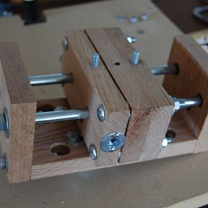
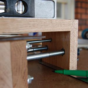
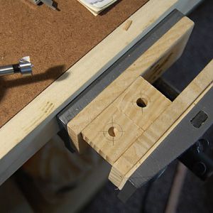
PIC 32 - Step 8
Jig Assembly - one 'Guide' bolt cut to size and channels cut in back of Z-axis Support so height above table can be adjusted.- MT native
- Media item
- carving drill foredom homemade jig press relief
- Comments: 0
- Album: Homemade Relief Carving Jig
-
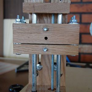
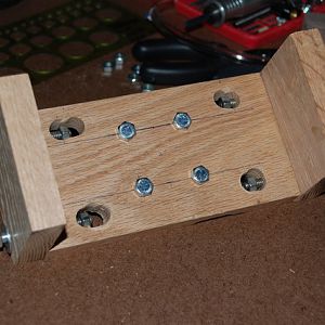
PIC 31 - Step 8
Assemble the Jig- MT native
- Media item
- carving drill foredom homemade jig press relief
- Comments: 0
- Album: Homemade Relief Carving Jig
-
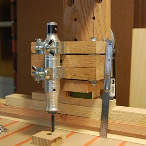
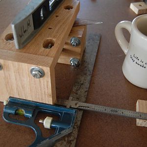
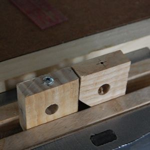
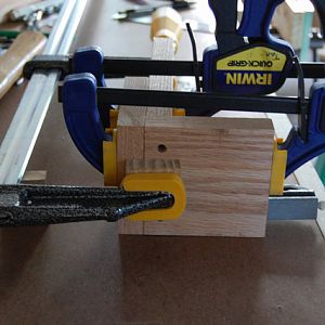
PIC 30 - Step 7b
Figuring out how much height adjustment I can get (using scrap wood spacers) before cutting channels in the ‘spine’- MT native
- Media item
- carving drill foredom homemade jig press relief
- Comments: 0
- Album: Homemade Relief Carving Jig
-
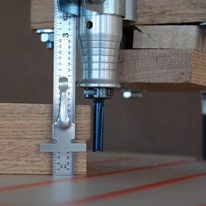
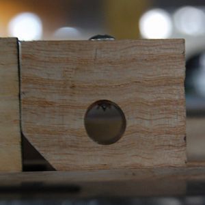
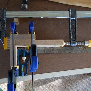
PIC 29 - Step 7b
If Z-axis Support were raised 1/2in then a max 1.5in block could be hogged-out to depth to 1/2in from bottom- MT native
- Media item
- carving drill foredom homemade jig press relief
- Comments: 0
- Album: Homemade Relief Carving Jig
-
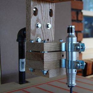
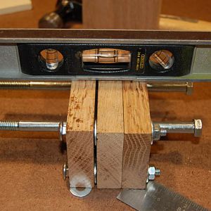
PIC 28 - Step 7a
Dry Fit to Frame to determine height above the table – Bit touches table NOT GOOD- MT native
- Media item
- carving drill foredom homemade jig press relief
- Comments: 0
- Album: Homemade Relief Carving Jig
-
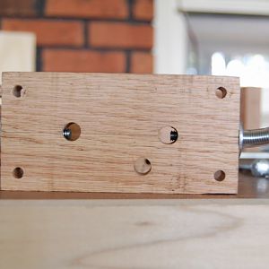
PIC 27 - Step 6d
Mark where the holes will be drilled. Repeat leveling, centering and marking for other end- MT native
- Media item
- carving drill foredom homemade jig press relief
- Comments: 0
- Album: Homemade Relief Carving Jig
-
PIC 26 - Step 6c
Make sure the Carriage is centered and square to the Z-axis Support. COFFEE HELPS ME THINK- MT native
- Media item
- carving drill foredom homemade jig press relief
- Comments: 0
- Album: Homemade Relief Carving Jig
-
PIC 25 - Step 6b
Add spacers to simulate the travel clearance you will have between the bolt heads in the Carriage and the ‘spine’ of the Z-axis Support- MT native
- Media item
- carving drill foredom homemade jig press relief
- Comments: 0
- Album: Homemade Relief Carving Jig
-
PIC 24 - Step 6a
Level the Carriage FRONT SIDE DOWN- MT native
- Media item
- carving drill foredom homemade jig press relief
- Comments: 0
- Album: Homemade Relief Carving Jig
-
PIC 23 - Step 5i
Closeup of a screw in the Horizontal Stabilizer- MT native
- Media item
- carving drill foredom homemade jig press relief
- Comments: 0
- Album: Homemade Relief Carving Jig
-
PIC 22 - Step 5i
Pre-drill for the screws that will secure the Guides horizontally- MT native
- Media item
- carving drill foredom homemade jig press relief
- Comments: 0
- Album: Homemade Relief Carving Jig
-
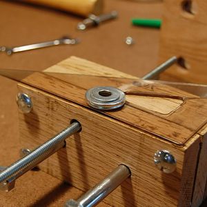
PIC 21 - Step 5h
Trim the corner of one of the Stabilizers to add clearance for the Depth Adjustment Rod- MT native
- Media item
- carving drill foredom homemade jig press relief
- Comments: 0
- Album: Homemade Relief Carving Jig
-
PIC 20 - Step 5g
Cut two (2) pieces for the Horizontal Stabilizers 1.5in x 1.5in and drill min 3/8in dia holes in centers for the Guides- MT native
- Media item
- carving drill foredom homemade jig press relief
- Comments: 0
- Album: Homemade Relief Carving Jig
-
PIC 19 - Step 5d
Z-axis Support dry fit - four bolts in center for attachment to the Floor Flange on the Frame- MT native
- Media item
- carving drill foredom homemade jig press relief
- Comments: 0
- Album: Homemade Relief Carving Jig
-
PIC 18 - Step 5b
Square the back (‘spine’) and ends of Z-axis Support before drilling pocket-holes - end view- MT native
- Media item
- carving drill foredom homemade jig press relief
- Comments: 0
- Album: Homemade Relief Carving Jig
-
PIC 17 - Step 5b
Square the back and ends of Z-axis Support before drilling pocket-holes - side view- MT native
- Media item
- carving drill foredom homemade jig press relief
- Comments: 0
- Album: Homemade Relief Carving Jig
-
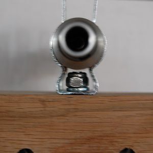
PIC 16 - Step 4b
Closeup of Foredom Hanger - FOLLOWUP - DO NOT USE ANYTHING ON HANGERS!!!! MESSY, STICKY, GOOEY YUCK!- MT native
- Media item
- carving drill foredom homemade jig press relief
- Comments: 0
- Album: Homemade Relief Carving Jig
-
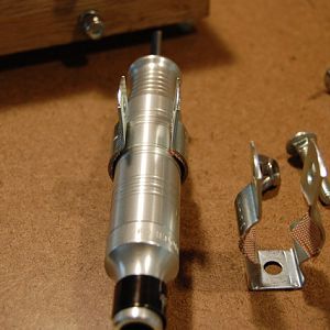
PIC 15 - Step 4a
Place the Foredom Handpiece in the Hangers and check to make sure there is clearance between the end of the carriage bolt and the Handpiece- MT native
- Media item
- carving drill foredom homemade jig press relief
- Comments: 0
- Album: Homemade Relief Carving Jig
-
PIC 14 - Step 3e
Dry Fit the Handle(s) into the Middle Section of the Carriage. Trim off the excess tubing- MT native
- Media item
- carving drill foredom homemade jig press relief
- Comments: 0
- Album: Homemade Relief Carving Jig
-
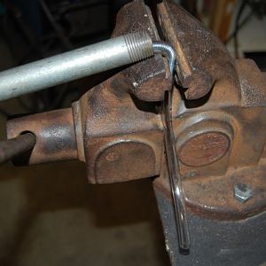
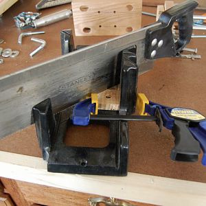
PIC 13 - Step 3d
Insert the 4in piece into 1/4in I.D. Vinyl Tubing and bend in a vise to make the Locking Handle- MT native
- Media item
- carving drill foredom homemade jig press relief
- Comments: 0
- Album: Homemade Relief Carving Jig