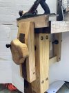
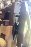
Bracket leg vise prototype

pop-pop

Man with many vises
Corporate Member
I am still intrigued by the cantilevered leg vise design that I used in the Hefty Benchtop Bench (Hefty benchtop bench). My next experiment is this Cantilevered Leg Vise. Since this build is experimental, I added a 5"x5" "wooden leg" to my existing 5"x5" right front bench leg for this vise:
IMG_5478 (1).JPEG


and the back end is thus:
IMG_5480.JPEG


The plywood pieces are laminated from some bed slats that a neighbor was throwing away. That plywood turned out to be the ideal material for these pieces. Note that the beam should have been longer to move the pillar to the end of the screw.

I did not make any detailed cartoons for this project but did use this concept layout.
cantilevered_leg _vise.png


The joint between the chop and the beam took three tries to get something that was strong enough. In order to salvage the chop from the first two failures, that joint is currently a lag screw and a cross dowel. I will be making a new chop and beam with probably a draw-bored mortise and tenon joint.
IMG_5463.JPEG


One of the toughest jobs that I have for a leg vise is holding my tall vise. Also, the constant strain on the beam-chop joint will be an informative test.
IMG_5485.JPEG


I plan on posting in Resources how to make a vise of this design after I get the leg-chop joint sorted out. All other aspects of this design seem satisfactory (at least initially).
 

Attachments

  • IMG_5478.JPEG
    IMG_5478.JPEG
    1.9 MB · Views: 72
  • IMG_5485.JPEG
    IMG_5485.JPEG
    2.8 MB · Views: 78
Last edited:

pop-pop

Man with many vises
Corporate Member
Awesome work! Is that a bench crafted vice hardware in one of the leg vise mechanisms?
In the tall vise in the last photo?

That is my design and has been replicated in three NCWW tall vise workshops in recent years. See Resources on this site for plans and instructions from those workshops.
 

Jack A.

Jack
User
Nice design! For the chop joint, have you considered 2 cross-bolts, fitted tightly into their holes? Maybe also consider 2 cross bolts at the beam-pillar joint. The loads in that design will be trying to rack both of those joints.
 

pop-pop

Man with many vises
Corporate Member
Nice design! For the chop joint, have you considered 2 cross-bolts, fitted tightly into their holes? Maybe also consider 2 cross bolts at the beam-pillar joint. The loads in that design will be trying to rack both of those joints.
The beam-pillar joint is a bridle joint and the shoulders and one bolt seem adequate so far plus the stress is much less than the other joint. This joint needs to be separable to disassemble the vise for repairs.

The beam-chop joint can be glued and that’s I am currently leaning toward M&T. Still thinking about it. Appreciate the input.
 
Last edited:

pop-pop

Man with many vises
Corporate Member
Since I was going to laminate the chop, I decided to mill ”semi-mortises” while I had access starting with roughing on the tablesaw followed by carefully fitting using these tools:
IMG_5624.jpeg


After glueup, the taper was smoothed using scrub, jack, and smooth planes. 3/8” chamfers were hand planed on the external edges.
IMG_5626.jpeg
 

pop-pop

Man with many vises
Corporate Member
Very nice. Will you need full-blown plans for it?
Not sure at this point. Since the leg and top thickness are bench dependent, so the drawing would need to be more conceptual rather than exact dimensions. Anyway, we have worked together before and I appreciate the offer and will think about how to go about documenting. See the concept layout in the first post in this thread as a starting point. I have added a bearing to the top of the pillar and will post about that soon.
 

pop-pop

Man with many vises
Corporate Member
Decided to call this design “Bracket Leg Vise” and renamed the thread.

Since every vise seems to need one more inch of travel, I chopped a recess into the leg for the nut to gain that inch. Note the extra clearance top and bottom to avoid binding.
IMG_5651.jpeg

IMG_5655.jpeg
 

pop-pop

Man with many vises
Corporate Member
Nearly done with this prototype. Here is a new turret with an R16 bearing replacing the plastic pad.
IMG_5666.jpeg


Two views of the bracket and turret assembled.
IMG_5668.jpeg

IMG_5670.jpeg


Front view of handwheel and chop.
IMG_5671.jpeg
 

Charlie

Charlie
Corporate Member
Now, I have never done anything like that. Lol.
After that happens you ask yourself, "why did I do that"?
 

pop-pop

Man with many vises
Corporate Member
With the 24” Acme screw that I had, this vise ended up with almost 13-1/2” of capacity. Note that there are no guide rods to get in the way.
IMG_5699.jpeg


Today’s tinkering was to add this bit of slippery plastic since with various loosenesses adding up, the bracket can sag a bit whilst opening the vise. Also, the loosenesses added a little rattle which I hate. The deflection was on purpose and we’ll see if that was a good idea over time.
IMG_5695.jpeg
 
Last edited:

pop-pop

Man with many vises
Corporate Member
Decided to call this design “Bracket Leg Vise” and renamed the thread.

Since every vise seems to need one more inch of travel, I chopped a recess into the leg for the nut to gain that inch. Note the extra clearance top and bottom to avoid binding.
View attachment 230496
View attachment 230495

Haven’t been in the shop much recently now that the hottest days have passed. Been doing yard work and other household tasks.

I have been using this vise when I can to look for any improvements needed. I did notice a bit of binding here and there (this design should never bind). Tracked the binding down to too small a vise-screw clearance hole in the leg and a thick spot in the bracket.

First, I decided recessing the nut was a not a good idea and removed the vise assembly from my bench to fix that whilst enlarging the vise-screw clearance hole through the leg. I plugged the square nut recess and redrilled a larger clearance hole. Didn’t have a steel washer to use as a thrust surface so I made a plastic one.
IMG_5806.jpeg


Next I identified the fat spots in the bracket and hand planed them to get some clearance. The bracket slides smoothly through the leg mortise all the way now.

Next step will be a housing for the square nut. It will be two-piece so that the nut can be accessed for cleaning or whatever without dismantling the vise.
 

pop-pop

Man with many vises
Corporate Member
Made the replacement nut housing today. It is split to facilitate accessing the nut if ever needed without dismantling the vise. This view is the side that faces the leg.
IMG_5809.jpeg


This is the nut housing fastened to the leg with 1/4” anchor bolts and nuts.
IMG_5826.jpeg


Here is the vise reassembled on my bench leg. Remember that in a new build the leg would be your bench’s leg rather than my bolt-on “wooden” leg. It works smoothly now after repairs.
IMG_5815.jpeg


The 7” handwheel was used because I had it. Some days it feels a little small so I may replace it with a larger one
 
Last edited:

pop-pop

Man with many vises
Corporate Member
During the designing, I had thought about chop camber tweaking. Today, I needed to add a little camber and the first step was to slot the pillar attachment holes upward in the bracket.
IMG_5833.jpeg


Added two pieces of laminate to lower the bracket slightly.
IMG_5834.jpeg
 
Last edited:

Premier Sponsor

Our Sponsors

LATEST FOR SALE LISTINGS

Top